Lets have a look. Intermittent welds are called out using Length and Pitch.
Complete Welding Symbol Explained Weld Joints And Welding Symbols Part 3 Youtube
Interpret welding symbols from a print.

. Be performed on the arrow side of the joint. However it is also important that shop floor personnel are able to read and understand the details of weld symbols. Shows the edge intersection or surface of a part on a drawing.
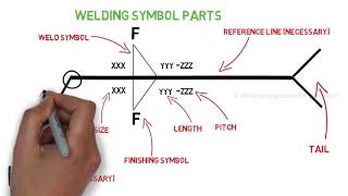
It is drawn at the end of the reference line opposite the arrow. MODULE 5 Reading Welding Symbols. Using a particular structure the welding symbols are drawn that explain the type and direction of the weld.
Chemistry Chapter E. It is essential that the rules of the standard used are correctly applied by drawing office personnel. Up to 24 cash back Drawing and welding symbol interpretation.
A scale drawing of a mechanical or architectural structure done with precision instruments. Also it helps to diminish the usage of too many welding symbols in one joint. Module 3 Drawing and Welding Symbol Interpretation Module 4 Shielded Medical Arc Welding SMAW.
It locates the flag at the original site in the country where the project demands to be completed. JS11 Joint Design Welding Symbols Student Handout for. This course covers the majority of information required to understand basic mechanical two-dimensional engineering drawings.
As noted above the number to the right of the diagonal line of the fillet symbol is the. Provides instruction in interpreting elements of welding prints drawings or sketches focusing on measurement American Welding Society welding symbols and fabrication requirements. 5 hours Two 25-Hour Classroom Sessions.
Spot and Projection Stud Seam Back and Backing Surfacing and Edge Welds. Groove Fillet Plug and Slot Welds. Learn vocabulary terms and more with flashcards games and other study tools.
This presentation covers symbols used in welding Brazing and. Various symbols have different meanings. The weld type symbol is typically placed above or below the center of the reference line depending on which side of the joint its on.
Point to identify show location andor the basis of a welding symbol. Arrow side of the joint. MODULE 3 Weld Symbols.
It usually contains information for which there is no provision elsewhere. Weld symbols are a very useful way of communicating welding requirements from the design office to the shop floor. Also it helps to diminish the usage of too many welding symbols in one joint.
MODULE 2 Lines and Weld Joints. Learn vocabulary terms and more with flashcards games and other study tools. Basic Parts of a Welding Symbol Weld Location and Symbol Orientation.
Basic drawing elements formats title block parts list revision block etc Part views multiview auxiliary and isometric Section views. A moving part or extent of motion. Plug and Slot Weld.
Views A drawing illustrating the part of an object one could see if standing directly in front. These symbols highlight the kind of work that should be conducted to finish the project of welding. Fillet weld symbols will ALWAYS have the vertical line of the symbol on the left.
This course aligns to SENSE Level 1 Module 3. Each symbol of welding that individuals see must. Reference line attached to the arrow.
Fillet welding refers to the process of joining two pieces of metal together whether they be. Information that appears to the left of the weld symbol refers to the. The welding symbol describes the whole thing while the weld symbol can be part of the welding symbol.
Students will understand how to prepare assemble and tack welding parts according to drawings or sketches using proper materials and tools. Identify and explain fillet and groove weld symbols. Will learn from this module.
A plug weld is a weld made in a circu-lar hole in one member of a joint fus-ing that member to another member. Module 5 Gas Metal Arc Welding GMAW GMAW-S Module 6 Flux Cored Arc Welding FCAW-GGM FCAW-S Module 7 Gas Tungsten Arc Welding GTAW Module 8 Thermal Cutting Processes. Weld on-site symbol The flag is a symbol to specify the on-site welding not in the workshop.
Weld between points symbol The drawing shows two points that require welding. How to Read Welding Symbols on Blueprints. The arrow between two points indicates the full-length welding between the marks.
The length of the fillet weld if it is not the entire length of the join is displayed to right side of the symbol. Finish and welding symbols. Explain how lines material fill symbols bar stock pipe breaks and revolved sections are represented.
Students will not receive credit for both WEL 233 and WEL 111. Students will understand how to prepare assemble and tack welding parts according to drawings or sketches using proper materials and tools. Identify and explain the various parts of a welding symbol.
Start studying SENSE Module 3 Drawing and Welding Symbol Interpretation. Drawing and Welding Symbol Interpretation Key Indicators 1 and 2. F Toes Face Root Legs and Throat.
29201-15 Welding Symbols Module One i Lesson Plans for Module 29201-15 Welding SymbolS Module One 29201-15 introduces the trainees to a broad range of welding symbols describes how they are structured and explains the basic rules to implement the information that the symbols convey. Drawing and welding symbol interpretation Must have a 75 to pass. A slot weld is similar to a plug weld except that the hole.
Right angle attached to either side of the reference line indicates a. Discuss basic welding detail drawings. Discuss basic drawing components.
Weld between points symbol The drawing shows two points that require welding. F Toes Face Root Legs and Throat. Weld on-site symbol The flag is a symbol to specify the on-site welding not in the workshop.
MODULE 4 Weld Symbols. Blueprint A written message conveyed from the draftsman to the workman containing technical information. Upon completion of this module the trainee will be able to do the following.
The welding symbol consists at least of a horizontal reference line has an arrow line pointing to the joint area and can have a tail. Read welding symbols on drawings specifications and welding procedure specifications. The symbol is interpreted as a simplified cross-section of the weld.
Showing an object in alternative positions. Start studying Module 3. This engineering drawing present weld type symbols and fillet weld symbols.
Start studying SENSE Module 3 Drawing and Welding Symbol Interpretation. The tail is the third weld symbol part. Plug and slot welds.
This info is very useful when each side comes with different details of the joint. Pr esent object views including isometric view multiview and sections used to create welding drawings. Download plug and slot welds in 3D to your phone.
Other sets by this creator. The graphic representation of a weld to be performed is called a. Safety and Health of Welders-Module 2.
Dimensions A process of illustrating the size of various objects.

Sense Module 3 Drawing And Welding Symbol Interpretation Flashcards Quizlet

Sense Module 3 Drawing And Welding Symbol Interpretation Flashcards Quizlet

Complete Welding Symbol Explained Weld Joints And Welding Symbols Part 3 Youtube

Sense Module 3 Drawing And Welding Symbol Interpretation Flashcards Quizlet

Sense Module 3 Drawing And Welding Symbol Interpretation Flashcards Quizlet
Module 3 Drawing And Welding Symbol Interpretation Flashcards Quizlet

Sense Module 3 Drawing And Welding Symbol Interpretation Flashcards Quizlet

How To Read Welding Symbols Part 3 Youtube
0 comments
Post a Comment